PTC Creo 10.0.0.0 with Manikin Libraries & HelpCenter (x64)

Free Download PTC Creo 10.0.0.0 | 8.5 Gb
Languages Supported: * English, עברית, 日本語, Ελληνικά, Français, Türkçe, Deutsch, Čeština, Русский,
Polski, Italiano, Magyar, Español, Slovenščina, 한국어, Português, Traditional 中文,
Simplified 中文, Brazilian Português, Slovenčina
PTC launched the tenth version of its Creo market-leading computer-aided design (CAD) software. Creo 10 helps you deliver your best designs in less time, with new composite tools and enhancements for electrification and ergonomics design, MBD, simulation-driven design, and manufacturing.
What's New Creo Parametric 10.0
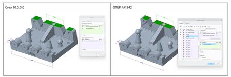
Improved STEP AP242 Support for References Included in Dimension Annotations
Description
You can now export additional surface references added to dimension annotations. You can do this for standalone annotations, annotation features and driving dimensions. When you include the annotations in the STEP AP242 export, all additional surface references are included in the export to STEP AP242.
When you import the STEP AP242 file in Creo Parametric or other applications, the defined dimensions references are included. When you evaluate the annotation, the included references are displayed.
Benefits
Previously, only the defined references that were used to create a dimensional annotation were imported or exported, and all additional references were lost. This improvement is useful when you want to capture proper semantic product manufacturing information (PMI). You must define the additional references for note annotations to capture proper annotation definition and included them in the STEP AP242 file.
This enhancement improves the quality and performance of rendering in Creo Parametric. It also maintains the design intent when you exchange the data containing note annotations with additional references between different applications.
xPTC Creo 10.0.0.0

Close
Manikin Individual Snapshots
Description
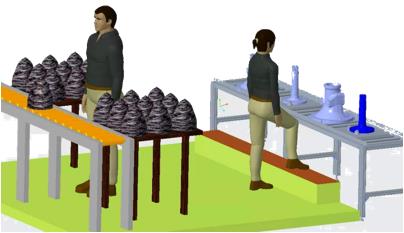
Manikins now support two types of snapshots, scene-level snapshots, and individual manikin-level snapshots.
- Scene snapshots capture all the constraints that apply to the overall design scene, including its components, and all the manikins in the model.
- Individual manikin snapshots capture the active constraints and component positions only for the specific manikin in its own position within the design scene.
The ability to capture individual manikin snapshots is useful when you work with multiple manikins in a scene, and you reposition and capture multiple manikins using snapshots. Capturing snapshots for individual manikins gives you control over each individual manikin's posture and position in a scene that contains multiple manikins.
You can use both individual-level snapshots and scene-level snapshots in the same scene, and you can switch between the snapshot types.

xPTC Creo 10.0.0.0
Close
Benefits
You now have control over snapshots for each individual manikin's posture and position in a scene with multiple manikins present, in addition to pre-existing overall scene snapshots controlling all manikins.
Manikin Placement Connections
Description
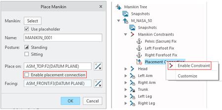
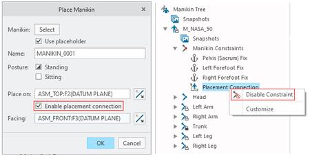
You now have better access to the manikin placement connections, which allows easier manikin repositioning and manipulation. The placement connections are always visible in the Manikin Tree, with the icon showing the connection status.
- If you do not enable the placement connection when you insert the manikin, then you can right-click the Placement Connection in the Manikin Constraints node of the Manikin Tree and select Enable Constraint.
- If you enable the placement connection when you insert the manikin, then you can right-click the Placement Connection in the Manikin Constraints node of the Manikin Tree and select Disable Constraint.
Benefits
There is now easier access and better visibility of the Manikin placement connections, which makes repositioning the manikin out of its placement position easier.
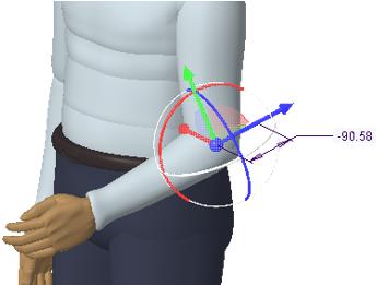
Manikin Measuring Joint Angles
Description
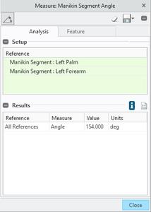
The angle between two adjacent manikin segments (limbs) can now be measured. The angle is measured between two lines that meet at the segments' connection point.
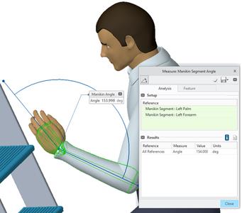
The selected segments' names are indicated in the Measure dialog box. The measurement can be kept as a saved analysis or a feature.
Benefits
You can now measure the angle between two adjacent manikin segments for ergonomic purposes.
Manikin Precise Dragging
Description
Manikin segments can now be reoriented with a precise 3D dragger increment, for both angular and linear control. When using the 3D dragger, an incremental drag value can be seen and manually changed to the desired number.
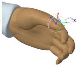
The display of this increment can be turned off from the dragger shortcut (right mouse button) menu.
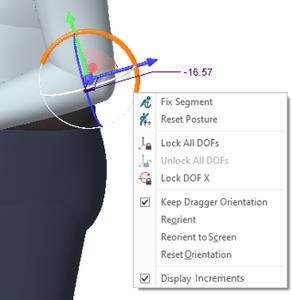
Additionally, there is an option to keep the dragger linear orientation locked after dragging, so multiple increments can be provided with the same orientation.
Benefits
Easily see and accurately control manikin segment positions with the 3D dragger.
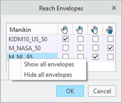
Manikin Reach Envelopes
Description
Manikins now support multiple reach envelopes. There is a reach envelope for the index finger, the middle finger, the thumb, and the center of the palm. Each of these four envelopes has a specific color.
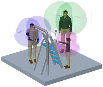
You can show one or more reach envelopes for each manikin in the scene. By right clicking the manikin's name in the Reach Envelopes dialog box, you can select to show or hide all envelopes for the selected manikin.
Benefits
You can now work with multiple reach envelopes for each manikin, and understand in more detail what the selected manikin's reach envelope is for the different hand locations.
Manikin Reaching to Planar References
Description
The ability to orient the reaching manikin segment has been added to the Manikin Reach tool. You align an anatomical plane on the manikin segment with a planar entity in the scene.
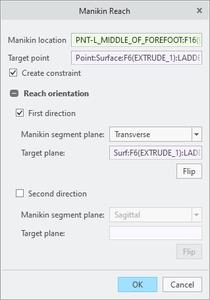
The two orientation constraints are optional. They are visible under the Reach constraint in the Manikin Tree.
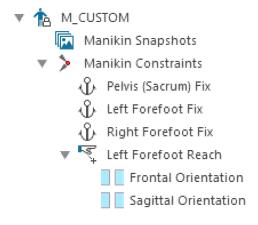
Benefits
By adding orientation constraints during Reach, the selected manikin segment orientation can be defined and constrained to prevent the solver from reorienting the segment.
Manikin Library as Inseparable Assemblies
Description
All library manikins are now stored as inseparable assemblies. The manikin body part components are embedded in the assembly file, resulting in only one single assembly file for each manikin.
Benefits
Data management is easier, with fewer objects to manage.
Improved Performance During a Drawing Retrieval
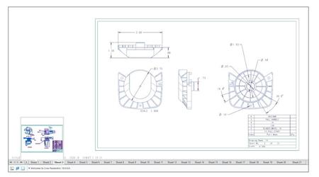
Description
Previously, the drawing sheet thumbnails were created during a drawing retrieval. This affected the retrieval performance when working with a multi-sheet drawing and complex models. With this enhancement, the drawing retrieval time has been improved by improving the logic for generating drawing sheet thumbnails on demand. The settings for the configuration option create_drw_sheet_thumbnails have been updated to control the creation of drawing sheet thumbnails. The values for configuration options are:
- yes-Thumbnails are generated on hovering over a drawing sheet tab.
- on_retrieval-Thumbnails are generated automatically during a retrieval.
- no-Does not generate thumbnails.
Benefits
This enhancement improves the performance of drawings during the retrieval for multi-sheet drawings and complex models.
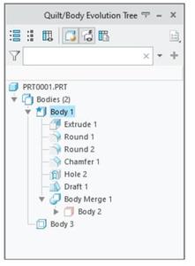
Enhancements to the Quilt/Body Evolution Tree
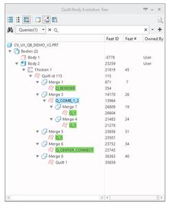
Description
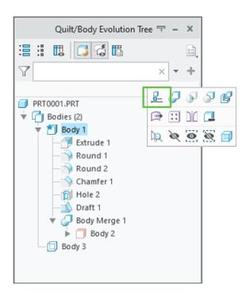
Additional capabilities have been introduced in the Quilt/Body Evolution Tree to improve the user interaction when working with the tree.
The following areas were enhanced in the Quilt/Body Evolution Tree:
- Drag and Drop action:
Ability to drag and drop bodies, quilts, and features from the Quilt/Body Evolution Tree to the custom groups in the Design Tree or custom groups under the Design Items in the Model Tree.
- Tree Columns
. Ability to configure and display tree columns.
. Ability to control the column visibility.
- Simple Search
. Quick search & filter capabilities like Model Tree and Design Tree.
. Support for search in columns.
. Support predefined type searches for bodies or quilts.
- Managing full tree settings in the .ui file:
Automatically save the settings for the Quilt/Body Evolution Tree to a *.ui file.
Benefits
These enhancements enable more productive usage of the Quit/Body Evolution Tree.
Enhancements to the File Open User Interface
Description
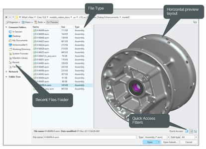
New enhancements have been added to the File Open dialog box to improve the user experience:
- A new column Type was added to the detailed view in the File Open dialog box. This column displays extended information about the file type or the application name (Part, Assembly, Neutral, Step, Creo View, and so on).
- A Quick Access functionality has been added for common file types. Previously, for filtering files by the file type, the file extension had to be entered manually in the search box. With this functionality you can group the listed files based on the selected type (Part, Assembly, and Drawing).
- The file preview has been optimized to display a horizontal layout of the selected file. Previously, the file preview was displayed only in the vertical layout. With this enhancement, both the vertical and horizontal layouts are now available for file preview.
Benefits
This enhancement provides improved usability when viewing, grouping, or sorting files and folders by type.
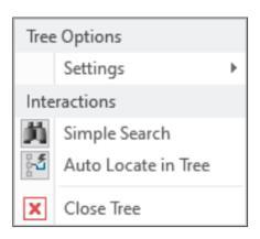
General Enhancements in the User Interface for Navigation Trees
Description
The user interface of the tree structures has been enhanced to improve a visual representation.
The enhancements to the user interface include:
- A new option to control the display of navigation tree lines for a better visual understanding of the structural nesting.
UI location:
1. Click File > Options.
2. In the Creo Parametric Options dialog box, click Windows Settings tab.
3. Under Navigation Trees Settings, select Show navigation tree lines.
- Enhancements in the workflows for closing trees. The workflows are now more aligned and common for all navigation trees.
- Simplification of group names to eliminate redundancy. The local group prefix for feature group names shown in trees has been removed.
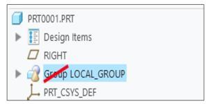
- Availability of the group creation command in the mini tool bar. The group creation command will be accessible in the mini tool bar even if a single feature is selected.
Benefits
These enhancements provide improved visual representation and better visual understanding of the structural nesting in trees.
Improved Workflow for Reorder and Restructure Operations
Description
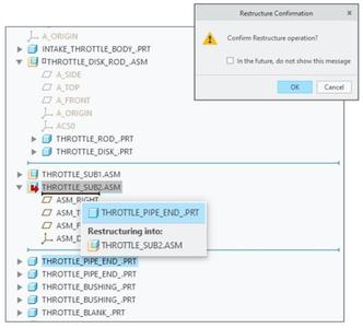
Previously, it was easy to unintentionally restructure the assembly when only a component reorder was intended. With this new enhancement, a workflow has been improved to better differentiate between the restructure and reorder operations.
The enhancements to the drag and drop actions include:
- A new tooltip to indicate which component is being dragged and where it would be restructured into.
- A new confirmation dialog box to confirm the restructure operation.
Value All and Confirm, has been added to the configuration option enable_dragdrop_on_components. When this value is selected, a confirmation dialog box appears for the restructure operations.
- Optimization of sensitivity zones and hovering time thresholds.
. The auto-expansion of target nodes has been reduced.
. Entry points to the restructuring workflow have been reduced.
Benefits
This enhancement reduces the instances of an unintentional restructuring when dragging and dropping components in the Model Tree.
New Capabilities for Non-Consumed Bodies and Quilts
Description
Previously, the Insert to Body and Insert to Quilt commands were available for consumed bodies and quilts only. With this enhancement, the insert commands are now available for non-consumed (consumed and active) bodies and quilts also. The insert mode is automatically activated, after the last contributing feature of the selected body or quilt, when these commands are used. Activation of insert mode sets the body as default body and unhides the body or quilt (in case it is hidden).
Benefits
This enhancement increases design productivity and unifies workflows for active and consumed geometric containers.
Rotational Symmetry Constraint
Description
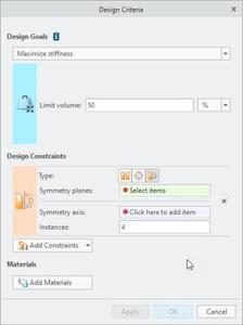
You can now use Rotational Symmetry as an additional geometric constraint in the design criteria of a generative study.
In a Symmetry constraint, you can now select planar symmetry, rotational symmetry, or both. When setting up rotational symmetry, you must specify the symmetry axis and the number of instances for the rotational pattern.
When running generative design optimizations, you need the ability to ensure that the optimized geometry is structured symmetrically around an axis. This symmetry may need to be applied in conjunction with the symmetry across a plane.
Benefits
The previous versions of Creo supported symmetry constraints only across a plane. This enhancement provides greater control over the geometry output of generative optimizations. It helps you generate designs that are radially balanced.
Measuring the Distance Between the Geometry and Hybrid Body
Description
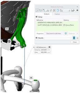
You can now measure the distance between a regular geometry and a hybrid body with the Measure tool.
With the Measure > Distance command, you can now select a hybrid body (a lattice or a generative body) as a reference for calculation.
The hybrid body can be used as a 'from' or 'to' reference in the distance measurement. You can select the hybrid body from the Model Tree or from the graphics window by using the Body selection filter.
Benefits
Previously, it was not possible to include a hybrid body in distance calculation. This enhancement allows you to easily calculate the distance between a hybrid body and other geometry. This enhancement improves usability of calculations for fit and function use cases.
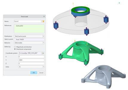
Support for Remote Force Loads in Generative Design
Description
In Generative Design, you can now define a force load through a point and apply it to the preserved geometry surfaces. The behavior of the total load at a point can be one of the following:
- Deformable-(Default) Allows the connected bodies to deform and does not add stiffness to the system.
- Rigid-Does not allow the connected bodies to deform and adds stiffness to the system.
You can also define the Deformable or Rigid behavior for moment loads. In this case, a remote point is not required. Instead, a centroid of the selected areas is sent to the optimization solver.
Benefits
With this enhancement, you can easily apply a distributed force over the selected reference where the load is applied. This enhancement captures the design intent without compromising the loading conditions.
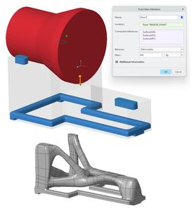
Support for Mass Idealizations in Generative Design
Description
In Generative Design, you can now define a point mass to represent a concentrated mass without stiffness and specific shape, and then apply it to the preserved geometry surfaces.
You can use a point mass idealization to study how the model behaves with that mass located at a particular location without specifying the entire geometry. A centrifugal or acceleration load is required to support a point mass idealization.
This enhancement is available in both Modal and Structural studies.
Benefits
With this enhancement, you can easily apply a mass load without needing to specify the entire geometry. This enhancement captures the design intent without compromising the loading conditions.
Auxetic Lattice-Two New Cell Types
Description
Two new auxetic cell shapes have been added to the Lattice feature in Creo.
- Auxetic uniform lattice can be controlled by the X angle parameter.
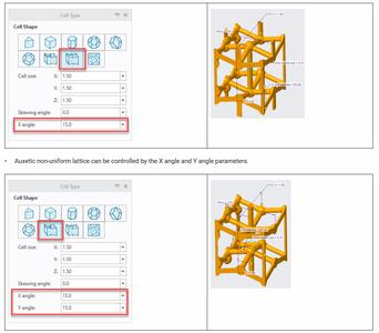
The auxetic cells enable you to create a beam-based lattice to produce structures with negative Poisson's ratio.
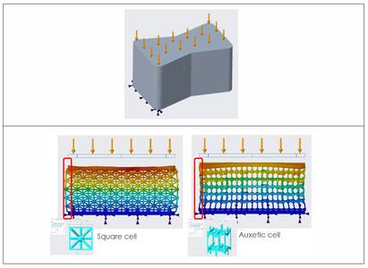
Benefits
- Create high energy absorption and fracture resistance meta-materials with properties that do not exist in nature. These can be useful in applications like body armor and medical devices.
- Create a beam-based lattice to produce structures with a negative Poisson's ratio.
- These capabilities are integrated inside Creo, without need to leave the Creo environment, and are fully associative.
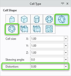
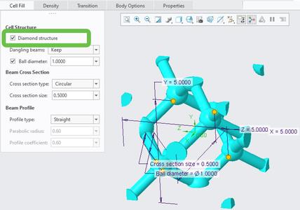
Rhombic, Rhombic with Diamond Structure, and Elongated Dodecahedron-New Beam-based Lattice Cell Types
Description
Now is possible to create rhombic dodecahedron, rhombic with diamond structure, and elongated dodecahedron lattice types. These capabilities are implemented in the regular lattice workflow. They are useful for the creation of medical devices with approved cell types, without need to leave the Creo environment, and are fully associative.
- Randomized nodes possible using the Distortion parameter
- Possibility to add a skew to the cell using the Skewing angle parameter
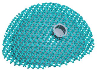
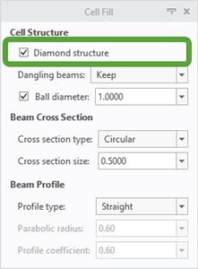
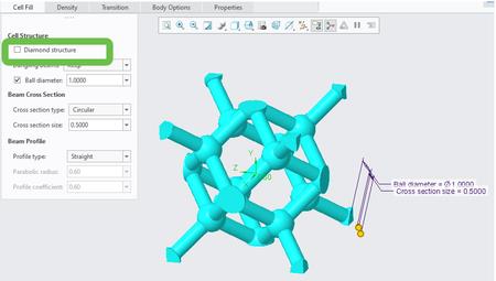
The Diamond structure option creates a sub-type of rhombic dodecahedron lattice that provides strength with fewer beams.
Without diamond structure:
With diamond structure:
Benefits
- Create medical devices using approved cell types right within the Creo environment.
- These capabilities are integrated inside Creo, without need to leave the Creo environment, and are fully associative.
IWP-New Formula-Driven Lattice Cell Type
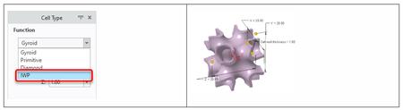
Description
A new formula-driven cell type has been added to the Lattice tool. IWP (I-graph and wrapped package-graph) is a TPMS (triply periodic minimal surface) that is used to create lattice with high structural efficiency.
Benefits
You can now create formula-driven lattice with the IWP cell type. This expands the options available for developing lightweight structures for thermal, fluid, and structural applications.
The IWP cell type creates lattice with high structural efficiency, useful in applications like heat exchangers or medical devices. You can easily create metamaterials with high energy absorption and fracture resistance.
Lattice with the IWP cell type can be created as part of the lattice creation workflow in the regular Creo Parametric environment.
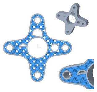
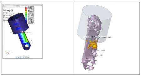
Formula-Driven Lattice with Varied Wall Thickness based on Simulation Results
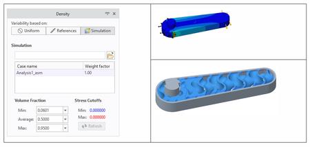
Description
The capability to create formula-driven lattice with wall thickness that varies based on simulation results has been added.
Benefits
You can now create formula-driven lattice with wall thickness that varies based on simulation results. FEA (finite element analysis) results can be mapped to a Creo part that contains lattice, and the wall thickness will vary according to the stress path.
The resulting lattice has higher density (thicker walls) in regions of higher stress, and lower density (thinner walls) in regions of lower stress. This assists in creating items such as heat exchangers that are also optimized to withstand structural loads.
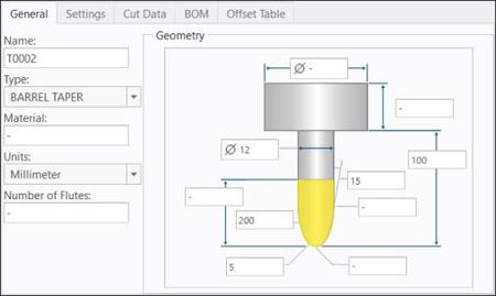
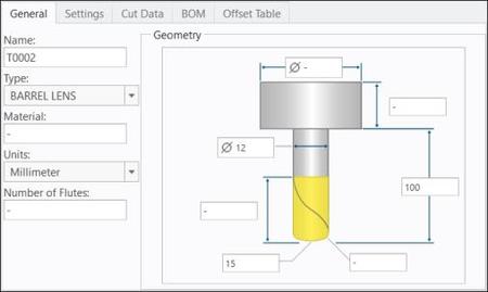
Support of Barrel Tools for Two New Finishing Commands: Wall and Floor 5 Axis Finish
Description
The barrel tools are supported for two new specialized finishing sequences:
- Wall 5 Axis Finish
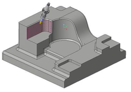
The following barrel tools are supported for Wall 5 Axis Finish:
. Ball Mill
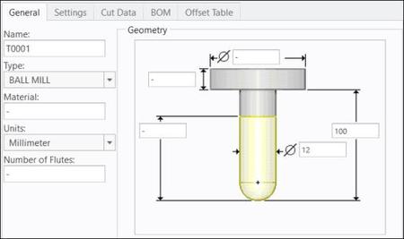
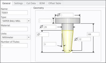
. Taper Ball Mill
. Barrel Tangent
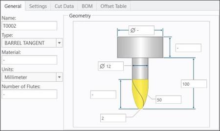
. Barrel Taper
- Floor 5 Axis Finish
The following barrel tools are supported for Floor 5 Axis Finish:
. Ball Mill
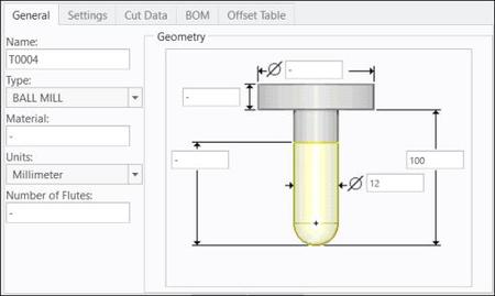
. Taper Ball Mill

. Barrel Lens
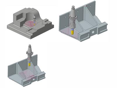
The barrel tools allow bigger stepovers using the same cutting speeds for high-quality surface finishes in a fraction of time. Dynamic disturbances are lower due to shorter tools.
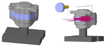
The new wall and floor 5 axis finishing toolpaths provide the following features:
- Automated generation of guide curves or an option to define guide curves
- Automated smooth and gouge-free tool axis interpolation
- Support for barrel tools and spherical mills
- Automatic tilting according to the tool contact point and collision avoidance
Benefits
The new barrel tools provide the following benefits:
- Allow a greater contact engagement between the cutter and the workpiece than conventional ball nose mills
- Achieve a small cusp height while using a relatively large stepover
- Drastically reduce the toolpath time on the machine
The new wall and floor 5 axis finishing toolpaths provide the following benefits:
- Reduce machining time
- Increase productivity as a higher stepover can be used with the barrel tools
- Provide a high surface quality as a low cusp height can be maintained
- Reduce programming time due to less user input and a faster toolpath calculation
Mill Volume for HSM Rough and Rest Rough Sequences
Description
The roughing high speed milling sequences can use a mill volume as a reference for machining. Selection of a mill volume is supported for Rough and Rest Rough NC sequences that include 3 axis and 3+2 axis.
Benefits
This easy-to-use functionality provides the following benefits:
- Reduces programming time
- Provides more control on defining the machining area in 3+2 axis Rough or Rest Rough NC sequence
- Provides better consistency across Rough and Rest Rough sequences
- Supports collision and gouge checks
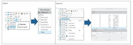
New CL Player for Synchronized NC Steps
Description
A new CL player has replaced the old and limited Menu Manager-based tool display for synchronized NC steps. This enhancement provides a modern CL player with extended capabilities for a full display of synchronized toolpaths without accessing the material simulation environment. The CL player provides a visual representation of the synchronized toolpaths. It also displays CL data of all heads to track line-by-line the execution of the synchronized toolpaths.
The new CL player provides support for the following:
- Solid tool display
- Step-by-step toolpath display
- Collision and gouge checks
Benefits
The new CL player with the extended capabilities is a replacement of the old Menu Manager-based UI.
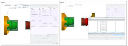
Modernized CL Player for Synchronize Command
Description
The modernized CL player is available for the Synchronize command. The Synchronize dialog box provides the new CL player when you click . This enhancement enables you to visualize the synchronized CL data when the tools are displayed in the graphics window.
Benefits
This easy-to-use functionality provides the following benefits:
- Reduces programming time
- Provides consistency in the workflow
- Enables a better visualization of synchronized toolpaths
Streamlined Holemaking Process
Description
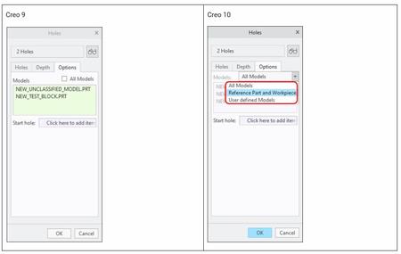
The workflow for the holemaking process is streamlined with redefined filters. This enhancement allows better control over which holes are considered by the automatic hole selection for the drilling operations.
The filtering has been redefined to easily exclude all parts in the assembly that should not be considered for drilling operations. It is now possible to filter the parts that are not classified as manufacturing objects such as reference model, fixture, or workpiece using the Reference Part and Workpiece option.
Benefits
This streamlined holemaking process saves time with fewer clicks and provides improved productivity.
Streamlined Manual Cycle
Description
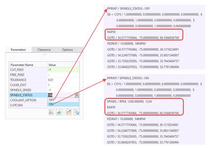
The workflow for the manual cycle is modified with less restrictions. With the streamlined workflow, the requirement for tool, clearance plane, mandatory parameters, and tool motions are no longer required. Valid parameters get inherited from a previous sequence or from a tool definition. Also, an additional parameter SPINDLE_STATUS with value ON or OFF is now supported for the manual cycle.
Benefits
The streamlined manual cycle workflow saves time with fewer clicks and provides improved productivity.
Ability to Define a Tool Offset for the Tool Adapter
Description
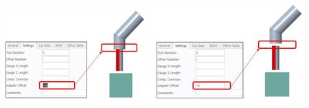
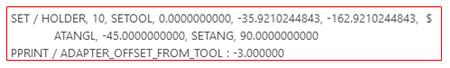
A new tool offset parameter has been introduced to displace the holder position along the tool axis. The Adapter Offset option has been added in the Tools Setup dialog box to support the displacement of the holder position along the tool axis. You can now modify the holder-tool assembly. The associated ADAPTER_OFFSET_FROM_TOOL parameter can be output in the CL file as a PPRINT statement.
Benefits
This enhancement eliminates the need to create multiple assemblies of holders and tools. The addition of the ADAPTER_OFFSET_FROM_TOOL parameter in the CL data makes the code clear to programmers.
CUTCOM Support at Each Slice in Area Turning
Description
This enhancement enables a CUTCOM statement at each slice in the Area Turning sequence.
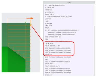
Benefits
This easy-to-use enhancement provides the flexibility to output CUTCOM statements either at each slice or at the beginning and end of the Area Turning sequence.
CLEAR_DIST Parameter Support in Area Turning
Description
The CLEAR_DIST parameter enables you to specify a clear distance that is above the workpiece surface at which PLUNGE_FEED ends and CUT_FEED begins. It provides more control over the application of the plunge feed.
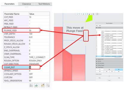
Benefits
This easy-to-use enhancement provides the following benefits:
- Maintains consistency across the Turning sequences
- Provides better control over PLUNGE_FEED
This enhancement also allows for faster machining, as three defined feeds are available for three different portions on the toolpath:
- Rapid feed for approach
- Plunge feed and Cut feed to remove a material
TURN_FOLLOW_TPROF_DIR Parameter Support in Area Turning and Groove Turning
Description
The TURN_FOLLOW_TPROF_DIR parameter considers the Turn profile direction to drive the cut direction in the Area Turning and Groove Turning sequences.
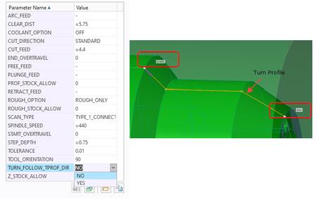
Benefits
This enhancement provides the flexibility to define the direction of the cut.
USER_OUTPUT_POINT Parameter Support in Area Turning and Profile Turning
Description
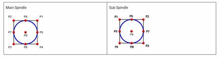
You can now specify a tool offset in the XZ plane of the NC sequence coordinate system for the Area Turning and Profile Turning steps using the USER_OUTPUT_POINT parameter. The toolpath output is offset by the NOSE_RADIUS value in the X-axis direction, Z-axis direction, or both X-axis and Z-axis directions.
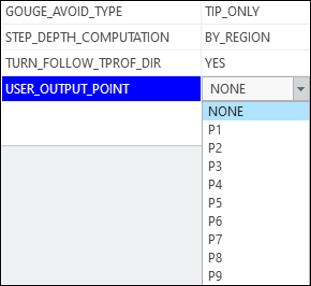
Benefits
The USER_OUTPUT_POINT parameter provides the following benefits:
- Flexibility to define exact tool offset point
- Ability to predict the output point
PPRINT Support for Tool Parameters
Description
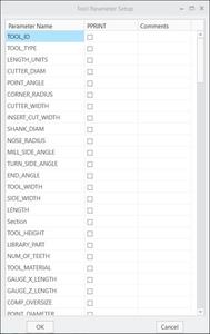
PPRINT support is now supported for all tool parameters. The tool parameters can be added in the CL data as PPRINT statements. A new Tool Parameter UI command containing all tool parameters is now available. The required tool parameters to be displayed in the CL data must be selected in the Tool Parameter Setup dialog box using the Tool Parameter UI command.
Benefits
This enhancement provides the following benefits:
- Flexibility to customize the CL data
- Support for all tool parameters
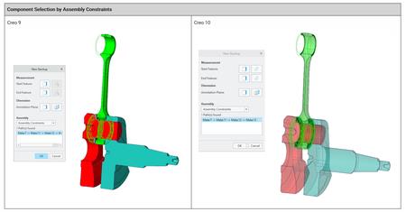
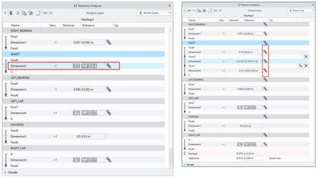
EZ Tolerance Analysis Enhancement: Overhaul of the New Stackup Dialog Box
Description
Previously, if you selected a wrong component or mating feature when defining a new stackup, you could not fix the wrong selection and had to start the workflow from the beginning.
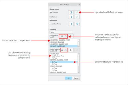
In this release, the New Stackup dialog box has been modernized for enhanced productivity and usability. The following enhancements have been implemented:
- Selected components and mating features are represented in live lists.
- Undo and Redo are now supported for components and mating features selections.
- Some icons were standardized.
Benefits
- When defining a new stack-up, you can now easily fix the selection mistakes.
- A clear indication is shown over your selections.
- You spend less time on recreating stackups due to wrong selections.
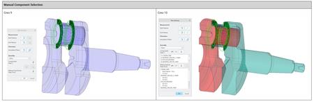
EZ Tolerance Analysis Enhancement: Improved Visualization of Models During a Stackup Creation
Description
Previously, in some scenarios it was hard to verify which components were selected correctly in the graphics area.
With this enhancement, when defining a new stackup, selected components are displayed with enhanced transparency and highlight.
Benefits
Enhanced visibility for the selected components during a stackup definition. This reduces mistakes made during the selection and stackup definition time.
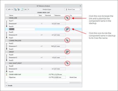
EZ Tolerance Analysis Enhancement: Link and Unlink a Component Name in the Stackup Table
Description
Previously, you had to manually rename the component names in the Stackup Table when the design was copied and the Creo models were renamed. This caused additional overhead and confusion if this step was missed.
With this enhancement, component names in the Stackup Table are by default linked to the actual part name in Creo. You can now decide whether to keep this link or break it, and then use the custom component names in the Stackup Table.
To control this naming behavior, click the new icons for each of the components in the Stackup Table.
Benefits
This enhancement provides an easy and robust way to keep in sync the Creo part name and its representation in the Stackup Table.
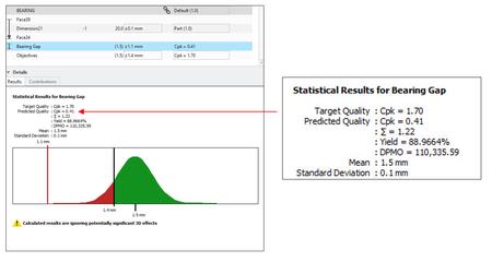
EZ Tolerance Analysis Enhancement: Analysis Results Description Includes All Quality Metrics
Description
In some scenarios, for reference, you may need to see other quality metrics that are not being used for the stackup analysis Description.
The stackup analysis results Description is always calculated based on a single chosen quality metric. Now it also includes all other quality metrics for reference (Cpk, Sigma, DPMO, %Yield).
Benefits
You can access valuable analysis information in the results Description in stackup reports.
EZ Tolerance Analysis Enhancement: Include Material Modifiers Effects in the Stackup Table
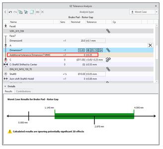
Description
When a position tolerance includes material condition modifiers, the standard allows for additional tolerance to be applied. This additional tolerance was already used in the stackup calculations; however, it was not represented in the Stackup Table.
With this enhancement, a new row has been added to the Stackup Table to represent the additional tolerance, when MMC Ⓜ or LMC Ⓛ are applied to a position tolerance for a feature of size.
Benefits
It is now easier to understand the impact of the additional bonus tolerances on the stackup.
EZ Tolerance Analysis Enhancement: Allow Selection of an Alternate Annotation Plane
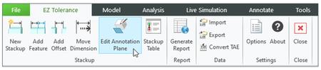
Description
Previously, it was not possible to change the annotation plane that was selected during a stackup creation without recreating the stackup. This enhancement enables you to change the currently used annotation plane on which the stackup annotations are placed.
Benefits
- Easily replace the annotation plane that is used for an existing stackup with an alternative plane.
- Less time spent on recreating stackups.
EZ Tolerance Analysis Enhancement: Support for Export of Stackup Data to the CETOL (.cxm) Format
Description
Previously, it was not possible to export analyses created in EZ Tolerance Analysis and leverage them in CETOL. EZ Tolerance Analysis now supports export of tolerance stackup data into the CETOL format (.cxm). This allows you to leverage the predefined 1D tolerance stackup data in the 3D stackup analysis software.
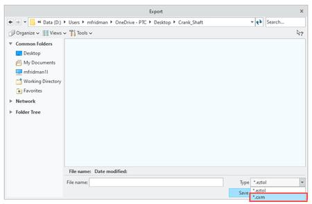
Benefits
Now, you can export tolerance stackup data into the CETOL format (.cxm).
EZ Tolerance Analysis Enhancement: Automatic Creation of a Part-Level Dimension Loop
Description
Previously, only one part-level dimension with the most efficient dimension path between the two mating features was included in EZ Tolerance Analysis Stackup Table to represent a linear dimension path. The remaining intermediate dimensions were not used by EZ Tolerance Analysis. You had to use the Add feature command to create intermediate dimensions.
This new enhancement detects existing intermediate linear dimension annotations with semantic references and automatically constructs a path in the Stackup Table to link to the dimensions in the model.
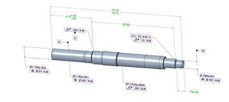
Benefits
Intermediate part-level dimensions representing a linear dimension path can be used directly by the stackup table.
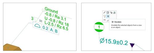
Relating Symbols and Surface Finish Annotations to other Annotations in Model-Based Definition
Close
Description
Previously, there was no easy way to relate symbols or surface finish annotations to other annotations in Model-Based Definition (MBD), and this type of placement was manual, non-associative, and not persistent when the parent annotation was moved. This enhancement introduces a new placement option for symbols and surface finish annotations that enables you to relate a symbol or surface finish annotation to other annotations in 3D models.
The new placement type has the following capabilities:
- Ability to relate the offset placement symbols and surface finish to other annotations in MBD.
- Ability of the related symbol or surface finish to inherit the same annotation plane as the parent annotation.
- Ability to behave as a group or stack for related annotations (mutual movement, assignments to combination states, and so on).
- Ability to highlight a parent annotation when a related symbol or surface finish is selected or vice versa.
- Ability to relate multiple symbols or surface finishes to a single parent annotation.
- Ability to unrelate a related symbol or surface finish from a parent annotation
Benefits
The benefits of this enhancement are:
- Easy and robust placement type for relating symbols and surface finishes to other annotations in MBD.
- New Model-Based Definition and Model-Based Enterprise workflows for inspection planning, tracking, and other use cases.
- Additional placement options for surface finish annotations that improve compliance to the detail drawing standards.
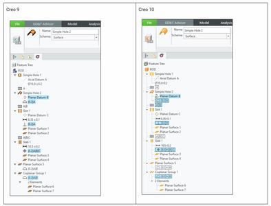
GD&T Advisor User Interface Enhancements
Description
GD&T Advisor icons have been modernized and adjusted to follow a new color scheme as well as Creo guidelines.
Benefits
Improved readability of GD&T annotations in the GD&T Advisor trees and icons updated across the entire GD&T Advisor application improve the user experience.
Improvements to the General Profile Tolerance
Description
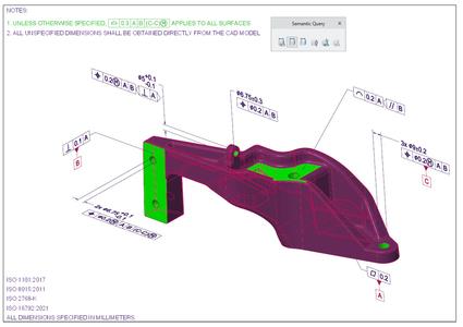
General Profile Tolerance (GPT) with semantic information is now available in Creo.
Previously, GPT was represented as a simple note, and none of its properties were reflected by its parameters.
GPT created with GD&T Advisor is now represented as a geometrical tolerance annotation type, which means that all properties of the annotation are also conveyed to its parameters.
Previously, all model surfaces associated with the general profile could be colored. However, the actual model surfaces were not added as semantic references to the annotation.
Additionally, GPT is now associated to the relevant surfaces of the model. This means that any model surfaces that are not otherwise specified with other GD&T annotations will be added to the general profile tolerance as semantic references.
The semantic references that are associated with a general profile tolerance are automatically updated with every model change. However, you can also manually update the semantic references of GPT using the new command Update General Profile references from the GD&T Advisor ribbon.
Benefits
With this enhancement, GPT now contains all relevant semantic references from the model. This helps to convey the true Model-Based Definition (MBD) state of the model for the downstream use.
GD&T Advisor Compliance to Detailing Standards: Support for Straightness and Line Profile in ISO GPS Models
Description
Geometrical tolerances Straightness and Line profile can now be used for ISO GPS models in applicable situations. Previously, GD&T Advisor did not support this type of indication for ISO models. Now, a message advises you when such indication requires an intersection plane indicator.
Benefits
Improved compliance to the ISO 1101 detailing standard.
GD&T Advisor Compliance to Detailing Standards: Control Over the Tolerance Zone Shape Modifier
Description
Previously, you had no control over the tolerance zone shape modifier for holes and spheres in ISO GPS models. Now, you can control the tolerance zone shape modifier for holes and spheres in ISO GPS models using the options SØ, Ø, or.
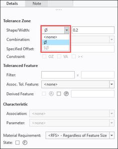
Note: When the shape modifier is set to, a message warns you that you need to add an orientation plane indicator to complete the definition.
Benefits
Improved compliance to the ISO 1101 detailing standard.
GD&T Advisor Compliance to Detailing Standards: Removal of the Drill Size from Threaded Holes
Description
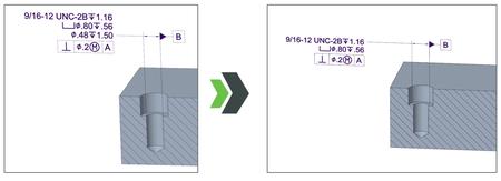
Previously, the drill size of threaded holes was displayed in ASME models. This type of indication was not desired by the users.
When using ASME models, it is a common practice not to show the drill size of threaded holes in the dimension indication. This is now supported by GD&T Advisor.
Benefits
Improved compliance to the ASME standard.
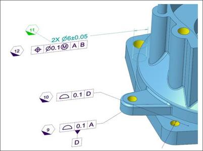
Support of Additional Feature Types for On-demand Dimension Creation
Description
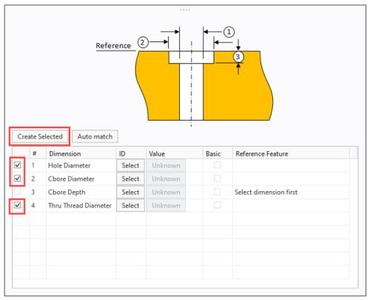
Previously, on-demand dimension creation was available only for some GD&T features. Now, this capability has been expanded to support the on-demand creation of diameter dimensions for multi-elements holes and shafts that include:
- Blind holes
- Drilled holes
- Counterbore holes
- Thru thread
- Blind thread
This enhancement is especially helpful when the holes must be annotated on the assembly level.
Benefits
When annotating assemblies with GD&T Advisor, often multi-element holes must be defined. Because a hole is defined in the part, its dimensions must be recreated for the assembly-level annotation. This is a time-consuming task.
With this enhancement, you spend less time on creating missing dimensions when annotating multi-element holes in assemblies or in imported geometry.
GD&T Advisor Improved Productivity and Usability: Support for Object-Action Workflow for Creating Tolerance Features
Description
GD&T Advisor now supports object-action workflow for the creation of tolerance features. With this enhancement, you can now select all model surfaces that should be included in the definition of a new tolerance feature, and then click Tolerance Feature in the ribbon to create it.
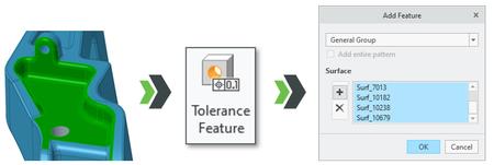
Benefits
You can select all model surfaces first to create a new tolerance feature.
GD&T Advisor Improved Productivity and Usability: Highlight Non-size Dimensions with Unspecified Tolerances
Description
A new contextual command has been added in GD&T Advisor to highlight non-size dimensions that have unspecified tolerances.
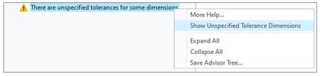
Benefits
With this new command, it takes less time to identify which non-size dimensions in the model don't have their tolerances specified.
GD&T Advisor Improved Productivity and Usability: Automatic Expansion of the Targets Tab
Description
Previously, you had to click to open the Targets tab to start defining it. Now, when the Datum from Targets option is selected during the functional feature definition, the Targets tab opens automatically for input.
Benefits
With this enhancement, fewer mouse clicks are required when defining a Datum from Targets in GD&T Advisor.
GD&T Advisor Improved Productivity and Usability: Automatic Matching of Dimensions to the New Scheme
Description
Previously, when updating the dimension scheme of a functional feature, the dimensions had to be manually matched again by performing an auto match.
Now, when you update the dimension schema, GD&T Advisor automatically matches the dimensions to the new scheme. For example, when updating the dimension schema of a hole feature from Basic Size to Toleranced Size, the dimensions will be auto matched.
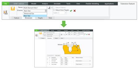
Benefits
This enhancement streamlines the workflow for creating functional features in GD&T Advisor, resulting in fewer mouse clicks for completing a feature.
GD&T Advisor Improved Productivity and Usability: Set a Datum Feature from the Contextual Menu
Description
You can now set applicable features as a datum feature using the new contextual command, directly from the advisor feature tree.
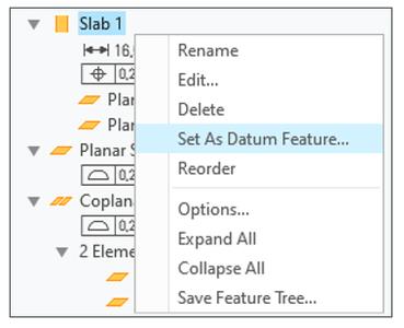
Benefits
With this new command, you don't need to edit a feature to set it as a datum feature. With fewer mouse clicks, you can now do it directly from the advisor feature tree.
Configuration Option to Specify a Custom Path for the GD&T Advisor Options File
Description
The new configuration option gdt_advisor_app_options_file enables CAD Administrators and users to define the location of an alternative options file that should be used by GD&T Advisor.
Benefits
This enhancement helps the organization to administer and manage the GD&T Advisor settings for all users in a consistent way.
Dimension Pattern-More Flexibility for Pattern of Pattern
Description
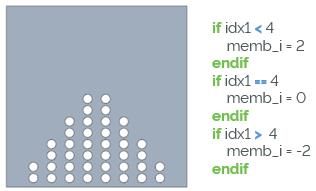
There is more flexibility in Dimension Patterns for nested pattern situations. This refers in particular to Pattern of Pattern use cases where the outer pattern is supposed to drive incremental changes in the pattern members count of the inner pattern.
In Creo 10.0, when you create a dimension pattern of a base (inner) pattern, you can also select inner pattern member dimensions as increment-direction dimension. This allows the outer dimension pattern to drive and increment the number of pattern members of a nested pattern. By default, the increment is 1. It can be set to any positive number including 0 where real values will be truncated to integer values. In case calculated pattern member values are smaller than 1, they will be set to 1. Pattern member dimensions can also be defined by relations.
In context of this enhancement, a previous general limitation on pattern member dimensions is removed. You can now set the number of pattern members to 1.
- Incremental increase of Pattern instances
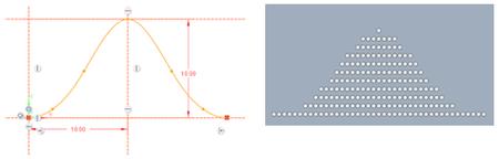
- Pattern instance count driven by relation
- Pattern instance count driven by graph
Benefits
This enhancement provides increased design productivity and usability for models that contain nested dimension and reference patterns.
Previously, Pattern of Patterns with varying numbers of member instances required more complex or time-consuming pattern definitions or workarounds through table patterns.
- Increment (idx) dimension can now be the pattern members dimension of an inner/nested pattern
. Members dimension is now a selectable dimension
. Default increment is 1
. Smallest evaluated pattern member value is 1
. Pattern member dimension can be driven by relations (including graph-based evaluations)
- Number of pattern members can be set to 1
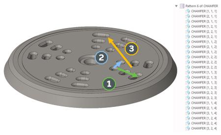
Reference Pattern-Improved Indexing
Description
The reference pattern indexing scheme in the Model Tree has been improved in Creo 10.0. The listed features underneath a reference pattern now index referenced feature and group patterns individually when both feature and group patterns are referenced.
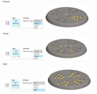
Benefits
The improved indexing of reference patterns allows better understanding of feature instances within a complex feature reference pattern.
Previously, referenced feature and group patterns had not been indexed separately.
Example dx 1, idx 2, idx 3:
idx 1: Feature pattern index (#1) - {1,2,3}
idx 2: Feature pattern index (#2) - {1,2}
idx 3: Group pattern index (#3) - {1,2,3,4}
Pattern Instance Parameters
Description
Two new Pattern feature parameters are introduced to provide access to the pattern member count:
- PTC_ACTUAL_PAT_MEMBERS
This parameter is created when you create a pattern or when you retrieve a legacy model that contains a pattern. It indicates the actual number of pattern members in a Pattern feature, excluding the omitted pattern members. It applies to:
. Pattern features of all types
. Pattern Recognition feature
. Multi-hole feature using a sketch as a placement reference
- PTC_TOTAL_PAT_MEMBERS
This parameter indicates the total number of pattern members in a Pattern of Pattern feature, excluding the omitted pattern members. It applies to:
. Pattern of Pattern (two levels)
. Pattern of Multi-hole feature (two levels)
. Pattern of Pattern of Multi-hole feature (three levels)
Does not apply to pattern of groups. For pattern of groups, use pattern recognition to indicate what to count.
The parameters are feature-level parameters that belong to the pattern header feature. The parameters can be referenced by a relation. They cannot be edited or deleted. The values are updated after pattern regeneration. They apply to all pattern types.
Benefits
- Easily access the number of active pattern instances.
- Allows parameter callout of active pattern instance count.
Previously, it was difficult to programmatically access the actual number of pattern members.
Hole Feature-Standard Parameters and Hole Note for Simple Holes
Description
You can now create parameters and a hole note for simple flat holes and simple drilled holes. The new parameters are driven by new .hol files for simple flat and simple drilled holes. If you add parameters, you can also add a hole note.
Benefits
In the Hole tool, simple holes are enhanced and more aligned with standard holes with two new options:
- Create parameters for simple holes.
- If you create parameters, you can also create a hole note for simple holes.
Previously parameters and hole notes were not available for simple holes.
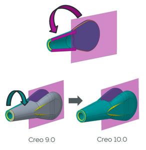
Divide Surface and Unify Surfaces Enhancements
Description
Divide Surface and Unify Surfaces features have been enhanced:
- Better handling of enclosed contours as part of the Divide
For each selected surface, regions that are entirely enclosed by, but not intersected by, the defining sketch projection or single closed chain are included in the resulting new surface. Previously, only surfaces that were intersected by the sketch projection or chain had been included.
The results are more predictable and better aligned with expectations. Depending on the situation, this can lead to slightly different results, in particular for the flip option.
. Creo 9.0
1. Enclosed contours that do not intersect the sketch
In Creo 9.0, there is ambiguity. The contours inside the closed sketch that do not intersect the sketch are not included in the geometric result, and remain with the original surface.
. Creo 10.0
1. Enclosed contours that do not intersect the sketch
In Creo 10, the results are predictable. All the contours inside the sketch are included in the geometric result, whether or not the contours intersect the sketch, and are included with the new surface.
- More stability in IDs
For typical cases, the surface ID of the surface created by a Divide Surface feature remains the same upon regeneration when dimensions change, leading to increased stability of the model. This applies to Divide Surface features created in Creo 10.0.
- Improved support of Dividing Edges in Creo Flexible Modeling operations
The behavior of dividing edges is more predictable during modeling operations and Round/Chamfer Recognition.

. Dividing Edges support for Creo Flexible Modeling operations such as Move, Offset, and Modify Analytic Geometry. Behavior of dividing edges:
- On unchanged surfaces:
Dividing edges that are extended/trimmed during the operation will remain, as long as they stay within their original domain of definition.
- On transformed surfaces, such as in Move/Offset:
Dividing edges are transformed as rigid edges.
- On involved Rounds:
Dividing edges are automatically removed.
- Tangent neighboring surfaces:
Tangency conditions are not propagated through dividing edges.
. Modifications to geometry created "on top of" Divided Surface:
The system attempts to restore/trim/extend dividing edges within the original domain of definition.
. Round and Chamfer related improvements:
- Recognition for Rounds/Chamfers with dividing edges is supported.
- Edit Round/Edit Chamfer and remove/recreate Rounds/Chamfers with dividing edges during Creo Flexible Modeling operations is supported, but dividing edges are automatically removed.
Note: Dividing edges that lie on rounds or chamfers, or on tangent neighbors to the modified surfaces, are removed during Creo Flexible Modeling operations.
- Remove restriction from Unify
Allow to unify all surfaces that are mathematically the same, even if the surfaces were created by means other than the Divide Surface feature. Legacy features will be upgraded to the new behavior upon Edit Definition.
Benefits
- Support of a broader range of design use cases involving Divide Surface and Unify Surfaces operations
- More predictable and stable geometric results during feature creation, regeneration, and geometric modification
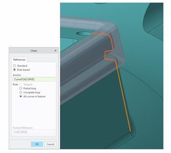
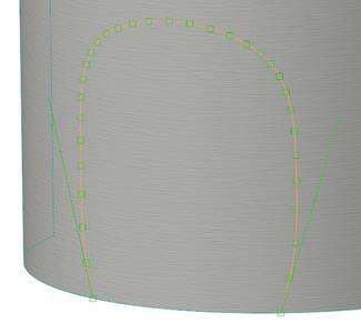
New Closed Loop Curve Feature
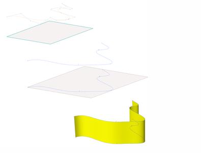
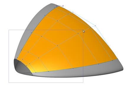
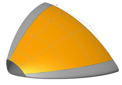
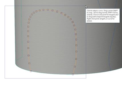
Description
Easily create a Closed Loop Curve on a surface, quilt, plane, or body. The feature allows the quick creation of closed loop curves based on system-guided solution choices. Use the Previous Solution and Next Solution buttons to cycle through possible solutions. The feature is available in the Part Modeling and Composite Design environments.
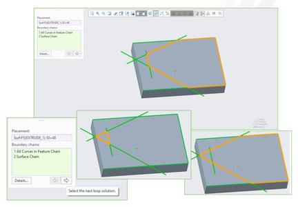
Benefits
You can easily and intuitively create a closed loop curve in one feature without the need to manually trim and merge all involved boundary chains.
Multibody: Combined Split/Trim Body Tool
Description
A new Trim option has been added to the Split Body tool, resulting in a combined Split/Trim Body tool. You can toggle between the Split and Trim operations within the same tool. When Trim is selected, the feature removes the split off portion, trimming the body.
The Trim option can be used with both the Splitting Object and Volume splitting methods. The name of the resulting feature depends on the operation, either Split Body or Trim Body.
Original model:
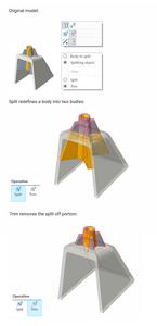
Benefits
- Easy access to a single tool to split and trim bodies
- Unified workflows to Trim a body by an object or by volumes
- Transparent feature naming in the Model Tree
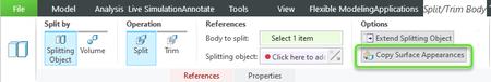
Multibody: Appearance and Reference Propagation for Boolean Operations
Description
Boolean Operations now provide more control over appearance and reference propagation from modifying bodies to modified bodies. All Boolean operations (Merge, Subtract, and Intersect) now provide the following new control options:
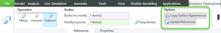
- Copy Surface Appearances
Copy appearances from surfaces of the modifying body to their counterpart surfaces in the resulting modified body. Considered counterpart surfaces include copied surfaces in additive operations as well as mating surfaces in subtractive operations.
Copied appearances include:
. Surface appearances
. Body appearances
These will be copied as new surface appearances on the modified body.
- Update References
. Reroute child feature references to surfaces of the modifying body to their counterpart surfaces in the modified body upon body subtract, merge, or intersect.
. A typical use would be to forward annotation references.
. This option is only available if the modifying body is consumed in the operation.
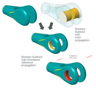
Benefits
Easily reuse appearance and annotation-based design intent during Boolean operations.
- Transfer color-coded information such as geometric tolerances or surface area indications when merging or subtracting bodies.
- Reuse fully annotated geometric bodies.
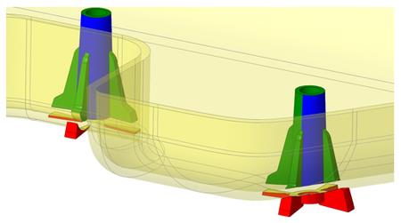
Multibody: Appearance Propagation for Split/Trim Body
Description
Split/Trim now provides more control over appearance propagation.
- Appearance propagation from the splitting object
. A new Copy Surface Appearances option is available for Split/Trim operations that are performed using a Splitting Object.
. It copies appearances from the surfaces of the splitting object to the counterpart surfaces of the trimmed body, or of both split bodies.
- Body appearance propagation to the new body
. The new body created by a Split operation inherits body appearance from the original body.
. Appearance changes are re-applied during regeneration, unless a user-defined appearance is applied to the body.
. Legacy Split features are upgraded upon Edit Definition.
Benefits
Easily reuse appearance-based design intent during Split/Trim operations. Transfer color-coded information when splitting or trimming bodies.
Multibody: New Flip Option for Split by Volume
Description
A new Flip option has been added to the Split/Trim tool that allows you to swap between two definition schemes when you Split by Volume.
- Default scheme
. Split-Identify volumes to split out into a new body
. Trim-Identify volumes to remove
- Flipped scheme (new)
. Split-Identify volumes to keep in the original body
. Trim-Identify volumes not to remove
Depending on the situation, the new definition scheme can help to define the desired outcome with fewer selections. It can help to define the feature in a more robust way, to help successfully regenerate subsequent operations on the feature, such as patterning.
Benefits
More flexibility to efficiently define the volume references for a Split feature for the most stable and predictable regeneration.
Broadened Support for Modernized Project and Offset Tools in Sketcher
Description
Broader support for the modernized Project and Offset tools initially introduced in Creo 9.0.
Benefits
The benefits of this enhancement include the following functionality:
- The All curves in feature collection rule is added to the Project tool. Note that this ruleisonlyevaluatedupon creation of the sketch.
- Modernized Project and Offset tools are now available in Sketcher workflows for trajectory-based features such ascurve pattern, sweep,flange, and more.
- There are multiple usability enhancements that ease reuse and manipulation of projected and offset geometry:
. When working with a composite curve that was created by projecting or offsetting geometry, you can now reference individual entities from the composite curve from within action-object based workflows for dimensioning and constraining.Specifically, these include the dimension creation tool, the constraints creation tools, and some other tools such as the concentric circle and concentric arc tools.
. EnhancedFillet and Chamfer tools automatically split a composite curve into two and insert the round or chamfer.
. The Mirror tool better supports compositecurves.
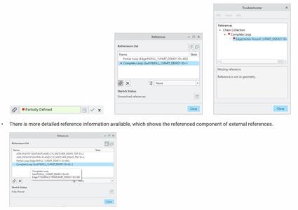
. Referencing an entity of a composite curve adds an explicit reference to the chain or loop that you can see from tools outside Sketcher, such as the Edit References and ReferenceViewer tools.
These Creo 10.0 enhancements combine the chain selection advantages introduced in Creo 9.0 with additional flexibility to work with the result of Project or Offset operations.
- You can project or offset geometry as construction geometry.
- Improved troubleshooting information is available for chain references used in the Project and Offset tools. This functionality helps you understand why a chain reference failed regeneration.
- While the Blend tool does not fully support the modernized Project and Offsetcapabilities yet, it now allows reference tocenterlines,coordinate systems, points, and construction geometry, in addition to solidsketched geometry from existing sections.
These functionality improvements make it easier and more flexible to use and handle 3D chain references inside Sketcher. Also, workflow alignments and the removal of limitations improve overall usability of the Project and Offset tools.
Improved Centerline Behavior in Sketcher
Description
Regeneration behavior of centerlines in Sketcher is enhanced.
Benefits
In previous versions of Creo, sometimes geometry would flip unexpectedly when rotating centerlines.
Sketcher is now enhanced to address this by preferring solutions where entities on a centerline stay on their originalside with respect to the center of rotation. This makes Sketcher regeneration upon dimensional changes more predictable, which enables easier creation of rotational patterns, resulting in increased usability and productivity.
For cases where there is no solution matching the preferred criteria, entities are instead placed on the opposite side of the centerline.
For sketches created in earlier versions of Creo, centerline behavior is upgraded to the new behavior when the sketch is modified.
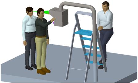
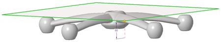
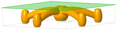
Visual Field Reflection Analysis
Description
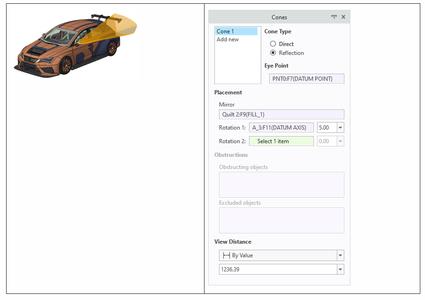
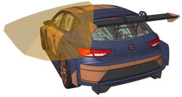
The Visual Field feature can now perform a reflection analysis, by looking at a reflective object. The resulting surface cone represents the visual field reflecting off the selected object, like a mirror. Additionally, the reflective object orientation can be controlled by adding a rotation value around one or two axes.
Benefits
You can now create a visual field surface cone by looking at a reflective object. This is useful when you perform an Ergonomics study and assess the field of vision from a given eye point through a reflective object like a mirror.
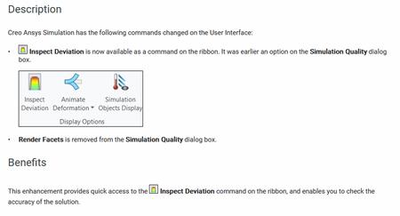
Description
Creo Simulation Live now supports the display of velocity results for a fluid simulation study, as vectors. There are also several options to control the display of vectors.
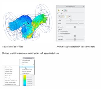
Benefits
- Powerful visualization options
- Expanded result types
- Expanded probe types
Creo Simulation Live Supports Contact Simulation
Description
Previously and by default, objects in contact are considered as bonded contacts. You can now define contacts between surfaces as Free, Bonded or No separation. No separation type of contact should be used to define contact surfaces. Free setting will cause touching surfaces to behave as if they have no contact.
For a particular type of contact to participate in a simulation study, you must define a contact for the study. Otherwise, all contacts within the model are considered as bonded contacts.
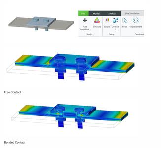
Benefits
- More accurate solutions where contact is important
- Can now define when touching surfaces are free
- Contact stresses can now be reported
Creo Simulation Live and Creo Ansys Simulation-Upgraded to Ansys 22R2 Solver
Description
Both Creo Simulation Live and Creo Ansys Simulation are upgraded to the latest Ansys 22R2 solver. This upgrade provides faster and more accurate solutions for all types of physics by using the most current Ansys technology.
Benefits
The new solver provides better GPU performance and a higher accuracy in results.
Creo Ansys Simulation and Creo Simulation Live-New Contact Detection
Description
The automatic contact detection method has been updated to have more ways to detect contacts between parts and bodies. There is support for one-to-one, one-to-many, and many-to-many type of contacts.
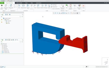
Additionally, during manual creation of contacts, the Repeat button automatically pre-fills the fields on the Contact Definition dialog box making it faster to manually create multiple contacts with the same properties.
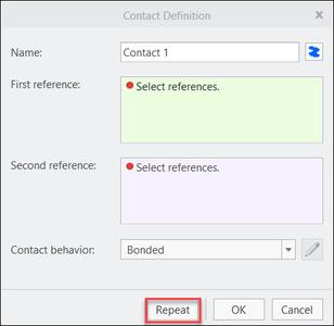
Benefits
- More efficient and fast detection
- Much faster setup
- Makes complex contacts much easier
Creo Live Simulation-UI Changes
Creo Ansys Simulation-Added Non Linear Contacts
Description
Creo Ansys Simulation has the following enhancements for the definition of contacts:
- Support for the following additional types of contacts:
. Frictionless
. Frictional
. Rough
- You can now define structural contact behavior which allows grouping of contacts.
- The following additional contact settings are also available:
. Formulation
. Selectable contact detection method - By radius or by a factor.
- Preview Simulation for all contact options
- Corresponding contact related results
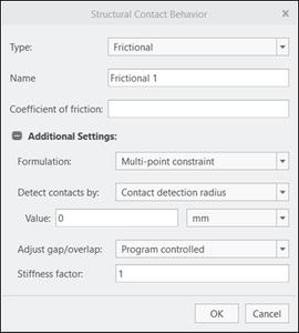
Structural Contact Behavior Settings
Benefits
- Very powerful and robust contact options
- Expands the number of use cases
- More realistic and accurate results
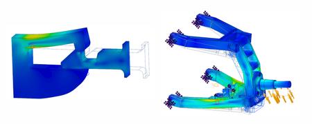
Creo Ansys Simulation-Support for Combined Structure and Thermal Studies
Description
Multi-physics studies were not supported earlier in Creo Ansys Simulation.This enhancement enables you to simulate thermal expansion by combining structural and thermal physics.
To define a combined or multi-physics study, first define a primary structural or thermal study. Then click next to Setup and select the Include Thermal or Include Structural check box which enables you to define additional physics from the ribbon.
You can clear the Include Thermal or Include Structural check box to return to the primary physics. Only steady-state thermal study is available for a multi-physics study.
The following figure shows thermal expansion in a model that is a primary structural study.
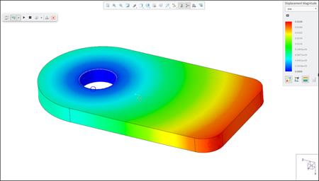
Benefits
This enhancement provides high-fidelity support for multi-physics. You can study thermal expansion and calculate thermal stresses for a primary structural study.
Creo Ansys Simulation-Non Linear Materials
Description
The following functionality is now supported. in Creo Ansys Simulation:
- Neo-Hookean hyperelasticity-This is used for plastic and rubber materials. Models with these materials can be used to study nonlinear stress and strain behavior with large deformations.
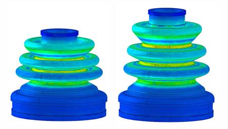
Large Deformation Study of a model with Neo-Hookean hyperelastic material.
- Linear orthotropic elasticity-Supported by models that have transversely isotropic materials. This is usable for woods, rolled materials, and any material that depends on direction.
- Bi-linear plasticity-Usable in large strain analysis. Elastoplastic materials can be defined using the Linear Hardening law.
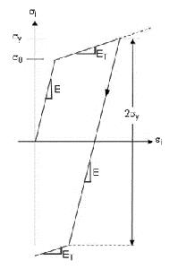
Stress-Strain Curve for bilinear elastoplastic material.
A Creo Ansys Advanced license is required for support for all the nonlinear material types.
Benefits
This enhancement supports creation of non linear materials and allows many use cases for different types of studies with a simple set up. Nonlinear materials created in Creo Parametric too are recognized and usable in Creo Ansys Simulation
Creo Flow Analysis-Results Improvements
Description
Previously, streamline animation could only be viewed as continuous lines. Streamlines had no indicators to depict direction or size. Streamlines now have indicators that are arrows or spheres. The indicators have control parameters.
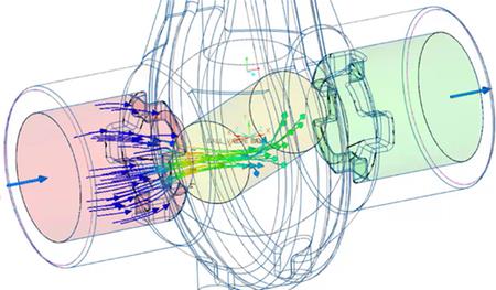
Single streamline animation is also a new feature. Streamline animation can be saved directly as a gif file. Orientation and post-processing settings can be stored as a simulation scene. All post processor settings and results are now saved with the project.
Benefits
- Enhanced visualization of streamlines.
- Enhanced visual effect for animation.
- There is no longer a dependence on screen recording.
- All results are stored for fast retrieval in the future.
Creo Simulate-Support for Multibodies
Description
Earlier, Creo Simulate allowed opening multi-body parts from Creo Parametric and running analyses on them, but did not allow defining simulation entities or objects on bodies.
This enhancement now allows the following :
- Selection of distinct bodies within parts for material assignment that may be different than the containing parts
- Support for all interface types between bodies -within or across parts
- Addition of bodies as valid reference type for heat loads
- Application of part-type mesh controls to separate bodies
- Definitions of measures that reference volumes can also reference bodies
Benefits
The enhancement supports a common workflow with improved control of bodies.
Creo Ansys Simulation-Export to Mechanical Command Available
Description
The Export to ANSYS Mechanical format command in Creo Ansys Simulation is now available by default. It was previously only available with a configuration option. This allows you to export a simulation model to the Ansys Mechanical format (.casdat)
Benefits
The Export to Mechanical command is now easily accessible, enabling export of a model to the Ansys Mechanical format.
Improved Projection of High Order B-Splines in Style Drop Curve
Description
Style has been enhanced to preserve the high order B-spline definition when projecting the curve onto a plane or planer surface. Previously, the projected curve defaulted to the minimum curve degree of 3, which might not meet the design intent.
You can now define a curve with a high curve degree, and when it is projected onto a plane or surface, the resulting curve will maintain that high order curve degree definition. Maintaining the high order curve degree of the original and the projected curve will result in a higher quality surface definition.
Benefits
The improved projection capability maintains design intent when creating curves and surfaces in Style.
Box Selection to Select Mesh Points in Style Surface Edit
Description
In Style, box selection has been added to the Surface Edit tool to help you select mesh points.
- You will now be able to use your mouse to drag a box to select a set of mesh points all at once, without the need to select them individually.
- Only mesh points on surfaces that were added as references in the Surface Edit tool will be available for box selection.
Dragging a box over a set of mesh points will automatically select the points, allowing you to manipulate the surface. Pressing the CTRL key and dragging a box will automatically:
- Select points that fall in the box and are not yet selected
- Deselect already selected points
Benefits
Easily select the desired mesh points to manipulate a surface.
Box Selection to Select Points in Style Curve Edit
Description
In Style, box selection has been added to the Curve Edit tool to help you select curve points.
- You will now be able to use your mouse to drag a box to select a set of points all at once, without the need to select them individually.
- Only points on curves that were added as references in the Curve Edit tool will be available for box selection.
Dragging a box over a set of points will automatically select the points, allowing you to manipulate them. Pressing the CTRL key and dragging a box will automatically:
- Select points that fall in the box and are not yet selected
- Deselect already selected points
Benefits
Easily select the desired points to modify a curve.
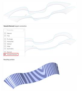
Smooth Curve Connection with G3 Acceleration for Mirrored Curves
Description
Style has been enhanced to enable a smooth curve connection with G3 - Acceleration for mirrored curves across a mirror plane.
Benefits
You can use the new Smooth Normal tangent connection type to enable smooth curves with G3 - Acceleration for mirrored curves across the mirror plane. When you design symmetrical models, this new connection type for curves will allow a smooth transition across the mirror plane.
The resulting surfaces will assume G3 - Acceleration connection, which will help to produce high-quality surfaces.
The new connection type reduces the need to tweak the curve control points to approximate acceleration connection.
Previously, setting the tangent connection for a curve normal to a mirror plane only produced a G2 - Curvature connection.
Normal tangent connection:
Style Curve on Surface (COS)-Additional Intersection Types to Snap Soft Points
Description
- Curve on Surface (COS) in Style has been enhanced to support additional intersecting geometry types when snapping the curve soft points.
The additional intersecting geometry types now include:
. Surface intersecting Curve
. Curve intersecting another Curve
. Plane intersecting a Curve
You can hold the SHIFT key and snap a COS soft point to the intersecting geometry reference.
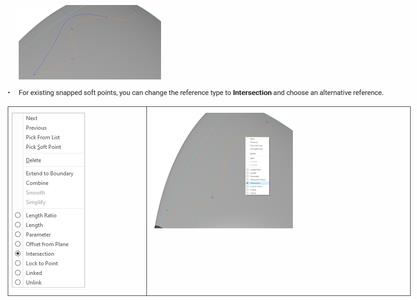
Benefits
Improved reference control for COS to capture your design intent.
Warp Stretch Tool-Define Length by Selecting a Reference
Description
You can now define length in the Stretch tool in Warp by selecting a reference.
Close
Benefits
In the Stretch tool in Warp, you now have the option to define the length by selecting a reference. This captures your design intent by dynamically updating the Warp feature if the reference position is modified. You can select datum planes, points, axes, coordinate systems, surfaces, curves, quilts, or facets as references to stretch the model in the specified axis direction.
Previously, you could only define length by using a scaling value.
Warp Spine Tool-Define Spine by Selecting a Target Curve
Description
In the Spine tool in Warp, you can now select a target reference curve to represent the geometry modification of a spine.
- Change the deformation target on the Spine tab to By Reference so you can select the reference curve.
- Editing the reference curve will automatically regenerate the Warp feature.
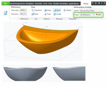
Benefits
Capture proper design intent to dynamically update the Warp feature if the reference positions are modified.
Rotational Symmetry in Freestyle
Description
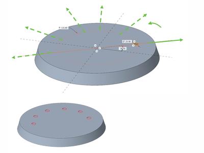
You can now use the new Rotational Pattern command in Freestyle to create rotational patterns of Freestyle shapes. You can select one or more shapes to pattern, choose an axis of rotation, define the number of members, and specify the angle between members.
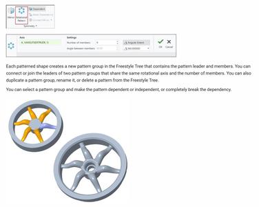
Benefits
This enhancement enables you to easily pattern complex shapes about an axis of rotation and maintain their dependency. It improves productivity and user experience.
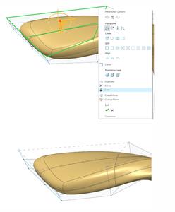
Locking Mesh Elements in Freestyle
Description
You can now lock selected mesh elements in Freestyle to keep a portion of the shape untouched during a modification.
You can lock faces, edges, and vertices of a shape while keeping the rest of the shape unlocked. The locked elements are displayed differently from the unlocked elements to indicate that they cannot be modified.
Note: Locking mesh elements is not possible in the resolution mode.
Benefits
This enhancement is useful when you work on a shape and want to lock it to preserve its definition and avoid any inadvertent modifications in the geometry. Sometimes, you want to modify only a specific portion of a shape and keep the other portion untouched. Previously, it was only possible to lock the entire shape.
This enhancement enables you to easily lock specific elements of a Freestyle shape to preserve their location while allowing modification of the other elements. This improves productivity and user experience.
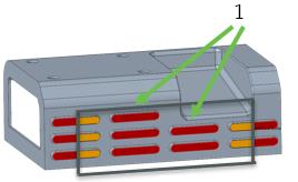
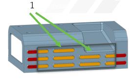
Paste Masks Support
Description
Paste Mask, or stencil data, on top and bottom layers of the board is now supported as context data.
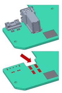
Benefits
Helps MCAD engineers review solder paste stencil for paste application during the assembly process.
ECAD Holes Parameters
Description
Allows you to set ECAD parameters when creating holes in the ECAD environment in the Hole feature user interface. Parameter values and defaults are customizable using the dedicated ECAD hole chart, ecad.hol file.
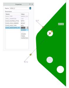
Benefits
- Ability to define different ECAD hole parameter defaults.
- Visibility of parameters during ECAD hole creation and modification.
- Ability to quickly modify parameters from within the Hole feature user interface.
Dedicated Cabling Tree
Description
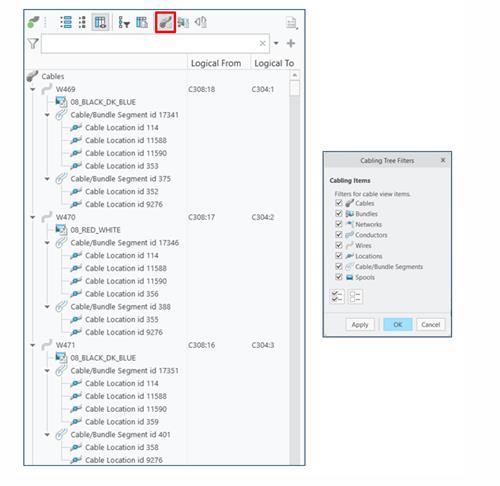
You can now use the new Cabling Tree to manage cabling data in the model. This tree is specific to the Cabling application.
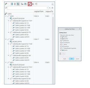
The Cabling Tree has the following three views: Cable View, Bundle View, and Connectivity View. These views allow you to see the harness structure in different ways. Each view is independent of each other and has dedicated filters and columns.
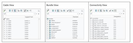
The Cable View displays all the cables, wires, overbraids, networks, and bundles in the active harness. You can expand the cables, wires, networks, or bundle nodes to get to the additional information, such as spools, segments, and location points for each segment.
The Cable View helps you immediately see all routed cables in the active harness. It enables an easy investigation and modification of routed cables.
xPTC Creo 10.0.0.0
Close
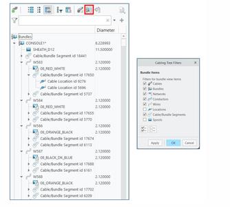
The Bundle View displays bundles and their contents in the active harness. Bundle contents can consist of additional bundles, cables, wires, and spools. This view also displays the cables that are partially routed through a bundle.
The Bundle View helps you easily find all the bundles and their content and properties in the active harness. It enables easy investigation and modification of bundles and their contents.
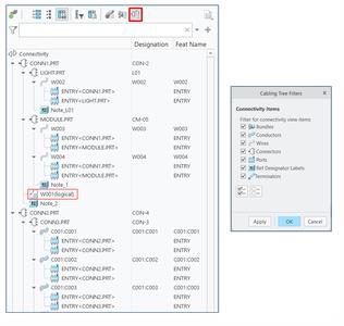
The Connectivity View displays all the designated connectors and the routing between them in the active harness. You can expand routed wires to display their ports on both ends. This view displays logical wires that are not yet routed as logical items. It also shows terminators and reference designation labels.
The Connectivity View helps you to easily see the connectivity structure of the active harness. It enables easier investigation and validation of the harness design.
Benefits
The Cabling Tree improves data management in cabling.
Previously, it was difficult to understand the harness structure because all elements were listed in the Model Tree as a flat list based on the regeneration order instead of a logical structure.
The Cabling Tree provides a better visibility into the harness structure with its independent views. Now, it is easier to locate harness elements for making modifications or creating new routes. This enhancement enables an easier creation, investigation, and validation of the harness design.
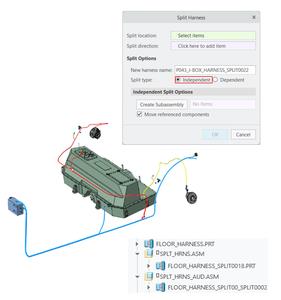
Split Harness Command
Description
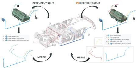
You can now use the new Split Harness command to split an existing harness into two separate parts that can be later merged back together. There are two ways to split a harness: Dependent and Independent.
The Dependent split creates two continuous harness parts in the same assembly. There is a parent-child relationship between the split harness parts. They share the same split location and cabling information, including the from-to information, logical references, and spools. You can remove the dependency between the harness parts by using the Remove Harness Dependency command.
Note: Although the dependent harness is considered continuous with its parent harness, both must be merged back to be flattened as a single harness.
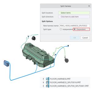
The Independent harness creates a new harness part that contains all the needed information to reuse in a different assembly. In this split type, the from-to information and the split location are not shared.
You can create an Independent harness in a new subassembly where all the cabling information from the original harness part, including spools, logical information, and skeleton, is automatically copied. You can also move the referenced components to the new subassembly.
Benefits
This enhancement enables collaborative harness design workflows. It allows the reuse of subsystems of a harness in different assemblies.
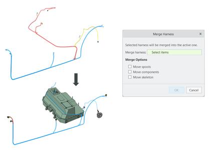
Merge Harness Command
Description
You can now use the new Merge Harness command to merge previously split harness potions back into the main harness after the harness design is complete. You can select any harness and merge it into the active harness. You can choose to move spools, referenced components, and a skeleton into the active harness assembly. Internally, merging is done by cable names or wire names. Therefore, before merging, you need to make sure that the naming is consistent in both parts for any newly routed wires or cables.
Benefits
This enhancement helps you restructure harness parts and merge back the split harnesses into a single piece for flattening.
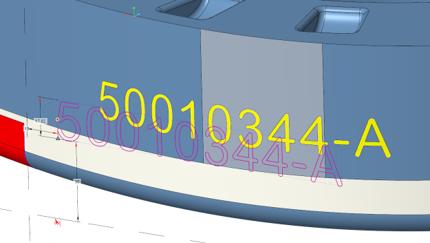
Reference Designations Propagation to Feature Names
Description
You can now automatically propagate the selected reference designations to feature names by using theexpression in the Propagate to Feature Name dialog box. Feature names are associated to wtParts in Windchill and further down in MPMLink, when managing the Parts list report. You can use theexpression in combination with any other text string. You can also remove feature names for the selected components by deleting the expression and leaving the feature name text field empty.
Benefits
This enhancement saves time by reducing the effort of manually assigning feature names for designated components to beused downstream in Windchill and MPMLink.
Improved Refit Reference Designators and Reorder Reference Designators Commands
Description
You can now use the improved Refit Reference Designators and Reorder Reference Designators commands.
Previously, the Refit Reference Designators and Reorder Reference Designators commands had some usability issues:
- Sometimes the Refit Reference Designators command produced unexpected results.
- It was unclear that a component needed to be selected instead of reference designators when using Reorder Reference Designators command, and it was inconsistent with the Refit Reference Designators command.
- For the Reorder Reference Designators command, there was no control over the leader length.
- The default value of the limit_ref_des_label_reorder configuration option was set to no, which caused some confusion to the users.
- The difference between these commands was not clear.
All these usability issues are now fixed.
- Both the Refit Reference Designators and Reorder Reference Designators commands are now added to the mini toolbar for faster access. Tooltips for both the commands are also updated.
- Both these commands act on the same selections, components or labels. However, if nothing is selected, the operation affects everything.
- The default value of the limit_ref_des_label_reorder configuration option is set to yes. The same configuration option is exposed as a check box in the Cables Display Settings dialog box.
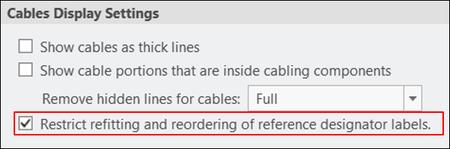
- A new cables_reorder_ref_des_len configuration option is added to control the leader size.
The Refit Reference Designators is updated for better placement of labels on the screen.
Benefits
This enhancement improves the usability of the Refit Reference Designators and Reorder Reference Designators commands. It aligns the user interaction so that both these commands work similarly.
Productivity and Usability Enhancements in Cabling
Description
You can now use the following productivity and usability enhancements:
- Updated Auto Designator dialog box
- Default bundle names
- Ability to insert or create components from the Cabling application
The new Feat. Name column in the Auto Designator dialog box displays the feature names and helps you easily compare them with the designation names. A new mismatch status is also added between the Reference Designation and the Cabling Component for easier validation of logical data updates.
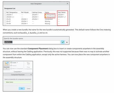
Benefits
These enhancements add flexibility of working with components from within the Cabling application.
PTC Creois the 3D CAD solution that helps you accelerate product innovation so you can build better products faster. Easy-to-learn Creo seamlessly takes you from the earliest phases of product design to manufacturing and beyond. You can combine powerful, proven functionality with new technologies such as generative design, augmented reality, real-time simulation, additive manufacturing. and the IoT to iterate faster, reduce costs, and improve product quality. The world of product development moves quickly, and only Creo delivers the transformative tools you need to build competitive advantage and gain market share.Creo 9helps you deliver your best designs in less time, with improvements to make every day more productive and every product more innovative.
PTC is proud to introduceCreo 10 and Creo+, the latest versions of our award-winning, powerful, yet easy-to-use CAD system. Creo helps you deliver your best designs in less time, with new composite tools and enhancements for electrification and ergonomics design, MBD, simulation-driven design, and manufacturing. Creo+, available via SaaS, provides innovative cloud-based tools for real-time collaboration and streamlined license management and deployment.
What's New in Creo 10 and Creo+
PTCenables global manufacturers to realize double-digit impact with software solutions that enable them to accelerate product and service innovation, improve operational efficiency, and increase workforce productivity. In combination with an extensive partner network, PTC provides customers flexibility in how its technology can be deployed to drive digital transformation - on premises, in the cloud, or via its pure SaaS platform. At PTC, we don't just imagine a better world, we enable it.
Product:PTC Creo
Version:10.0.0.0 with Manikin Libraries & HelpCenter
Supported Architectures:x64
Website Home Page :www.ptc.com
Languages Supported:multilanguage
System Requirements:Windows *
Size:8.5 Gb
Buy Premium From My Links To Get Resumable Support,Max Speed & Support Me
Rapidgator
http://peeplink.in/0b0385b33ab1
Uploadgig
p601u.setup.part1.rar
p601u.setup.part2.rar
p601u.setup.part3.rar
p601u.setup.part4.rar
p601u.setup.part5.rar
NitroFlare
p601u.setup.part1.rar
p601u.setup.part2.rar
p601u.setup.part3.rar
p601u.setup.part4.rar
p601u.setup.part5.rar
Links are Interchangeable - Single Extraction
Free Download PTC Creo 10.0.0.0 with Manikin Libraries & HelpCenter (x64) is known for its high-speed downloads. It uses multiple file hosting services such as Rapidgator.net, Nitroflare.com, Uploadgig.com, and Mediafire.com to host its files